With lots of new projects on the horizon, we thought we’d share more about our design process and how we get from the floor plan stage to the photorealistic rendering stage. Though our photorealistic renderings are a visualization tool, they are often not seen by our clients until we are almost finished with the documentation portion of our work. Here’s how we work:
The development of our projects is separated into sequential phases. The first three phases are led by the architect. These phases are DESIGN, DOCUMENTS and PROCUREMENT. These are also known in industry contractual terms as Schematic Design, Design Development, Construction Documents and Bidding. The remaining phase is led by the Contractor and we call it CONSTRUCTION, with the Architect’s role technically referred to as CONTRACT ADMINISTRATION. I’ll break down the first two phases quickly and then show you an example of how our design work turns into those pretty renderings you see on Instagram.
DESIGN
In the design phase, our goal is to lock in the floor plan and general massing. Small tweaks can be made after we finalize the design, but we’d like for 80-90% of the layout to be pinned down before moving into the DOCUMENTS phase.
Other deliverables in the DESIGN phase are concept boards illustrating the stylistic concepts that will guide decisions in the next phase. If required, we may review the design with any historic neighborhood commissions.
DOCUMENTS
In the DOCUMENTS phase, we engineer the structure (again, making it all more important to lock in a floor plan) and we select and detail of all the materials and fixtures on the project so that everything is spatially and technically coordinated in the drawings for the trades. The DOCUMENTS phase is also when the drawings are issued for permit. We make any adjustments to the plans that the City requires before issuing the plans for the BIDDING phase.
EXAMPLES
Let’s take for example our St. Charles Avenue Pool House Project. Below is an example of our visualization tools in the DESIGN phase.

Seen above is a Revit rendering showing basic design concept. This rendering will accompany a finalized plan.
Below is an example of our visualization tools in the DOCUMENTS phase.

As our work develops through the DOCUMENTS phase we make more and more specific choices, and those decisions are incorporated into the model as we develop our drawings. As you can see between the rough rendering in the DESIGN phase and the more realistic rendering in the DOCUMENTS phase, we made a few design tweaks as we honed in on the details. Realistic visualization and modeling forces the development of many small details that could be fudged or were not evident in the sketchy model. The stairs, the cornice detail, and the door design were all adjusted, but the overall design concepts and plan did not change.
NEXT, let’s see how the interiors of this project developed.
First, we need to define a design strategy using detailed images of other projects with aspects that we would like to incorporate into a holistic interior approach.

We look for images on Pinterest to help build a story board or concept board that depicts the overall vibe of the project.
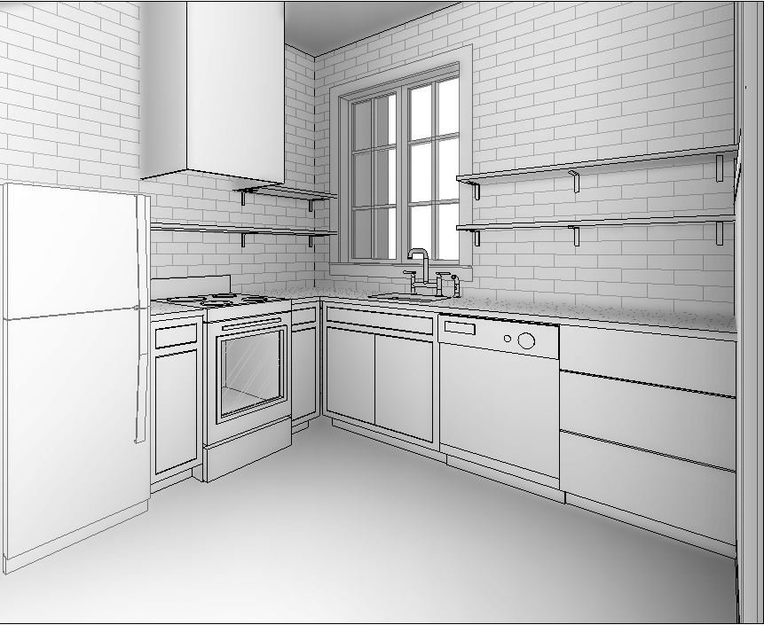
We begin modeling the components. In this stage, everything is in black and white.

Once all of the components are built, we will add the material and color. This is where the real visualization fun begins!

The above image is the final design we landed on; however, there were many iterations of this kitchen that came after the black and white stage, but before the final. This tool is great for helping clients visualize all the materials and finishes next to each other and how it ties together with the architecture.
Another example
Below are some renderings showing the difference between our DESIGN phase renderings and our DOCUMENTS phase renderings.
In the DESIGN phase, we are still testing out ideas

In the DOCUMENTS phase, we are testing out materiality and finishes

In the DESIGN phase, we look at big picture ideas this included massing and scale for this Irish Channel project.

In the DOCUMENTS phase, we add materiality and details that make the project special.
It’s important to remember that every project is different with a different set of design goals, so the renderings at certain milestones in the project may look further or less developed than other projects. New construction projects may address the exterior prior to interior where renovations may address interior form and materiality prior to the exterior development.
Spring Design Projects Keeping Us Busy

Last year we published a blog about our how our Quarantine Design Projects are keeping us busy. This year is no different. With so many exciting things going on from construction to consultations, we haven’t had much time to share our content. Here’s an overview of what’s happening over at Studio BKA
Read MoreRuby Slipper Mid-City
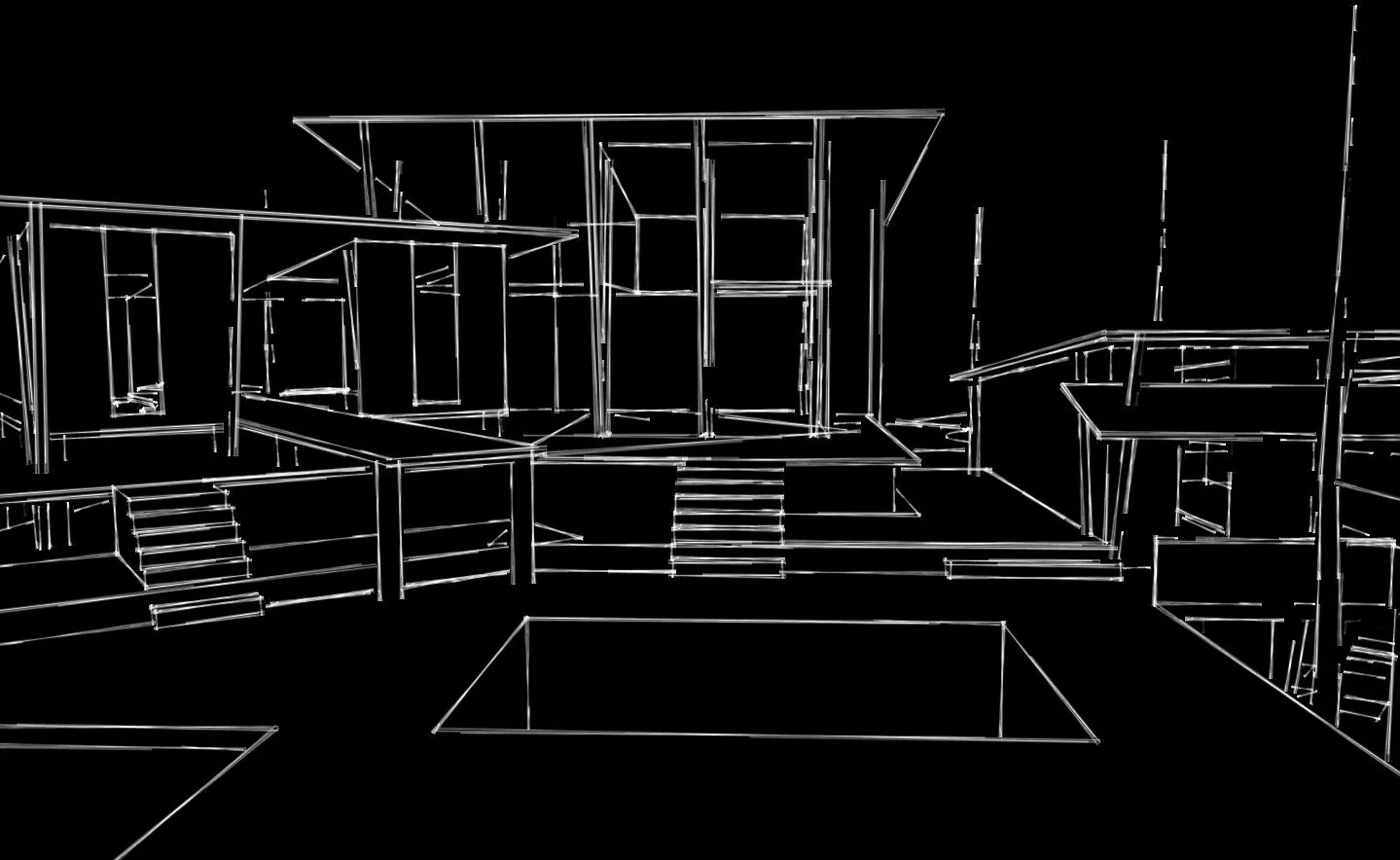
Here's a flythrough rendering of a project we're currently working on in Mid-City, coordinating with structural, MEP and food service equipment consultants to create an information model that coordinated equipment in tight spaces, produced construction drawings and provided the zoomy experience you see here!
Journal of the Revit Noob: The Data & The Dream!
What is BIM and why is it being implemented?
As if you were building a structure in real life, BIM, otherwise known as Building Information Modeling, is a technical software that graphical builds components of a model, as opposed to illustrating the design intent as architects have been doing for decades. BIM is being used worldwide by AEC firms for several reasons including increasing productivity, streamlining workflow and minimizing risk on projects.
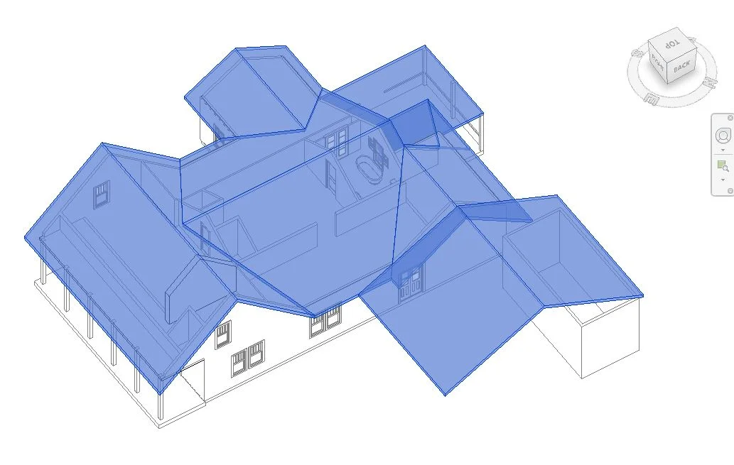
Learning about Revit roofs by working with existing conditions.
So, what's my take on the program?
Diving deep back into my vault of colorful memories from my time as architecture student, I don't think any of my successful projects came to life because I was thinking about how to build a footing properly to take on the massive loads created by a crazy cantilever I designed. In fact, knowledge of construction was only briefly touched in school and most of my learning came about in the years following graduation. The best architects are those with experience and knowledge of construction means and methods, but also know that implementing all that practical knowledge in the early phases of the design process can be like having the first discussions of AMC's "Breaking Bad" plot twists without having developed the characters first. I don't think the writers sat down and created some of the best drama on television, without fully conceptualizing their characters first. I don't know, you tell me, Vince Gilligan.
Despite what is being said about the major disconnect between the imaginative right-out-of-college BIM draftsman and the talented, experienced project manager whose time on drafting programs are limited as they advance into more senior roles. We, the experienced project managers, were once the right-out-of-college draftsman and believe both generations are imaginative. For me, the disconnect is the expectations of the software. As a beginner in Revit, but an experienced project manager, I found myself frustrated with basic functions or what I call, road blocks, on a daily basis. My biggest concern was that these road blocks resulted in discouragement and lack of creativity.
So, what can we do about it?
To have the best results in Revit, I needed to separate the data and the dream! The dream comes first and should take shape the way we see it with hand sketches, rough layouts and shapes...not the way I believe I must to stay productive and efficient as a firm. I, the dreamer, should choose the tool to craft my art.
The data is the key component in bringing our dream to life. Typically, we develop our dream into a design that takes conceptual shape and gets approval by an owner, then a trial and error process of details and specifications formulate which advance our dream. Hundreds of micro decisions are made along the way, stretching and pulling our dream into many forms until it has taken its final shape. Until I know what is final about my dream, I don't use BIM (yet).
While I'm learning about all the advantages the BIM provides, I have also had to strategize my own workflow to allow me to stay creative and encouraged and productive. When my dream is defined enough that I feel I know enough to put it into the BIM, then I'm not learning skills and evaluating design at the same time, and all is good in the world. It helps greatly to have guidance as to when and where to begin to drop things into the BIM from an experienced voice.
I wear many hats running my own architecture studio. In the mornings, I am social media director, marketing manager, administrative assistant and principal decision maker. Some afternoons, I am a draftsman and other afternoons, I am a designer and creator. Through all the different digital tools I use all day, my thought processes remain the same, except now that I'm adding BIM Student to the list, my processes - my marketable product - hit a road block and I can feel stuck. I use BIM to the point I'm comfortable, and use other tools to get over the hump; but I keep learning so that one day I'll have the momentum to go straight from dream to BIM, with no road blocks in sight!
Journal of a Revit Noob: View Range Illustrated
I was having a little difficulty understanding the VIEW RANGE settings which is an important tool in setting up your views, so I thought a visual guide may do me (and you) some good! I'll jump right into it.

- Double click into your view and refer to your PROPERTIES tool bar. You will see an "Edit" box under EXTENTS. Click it.
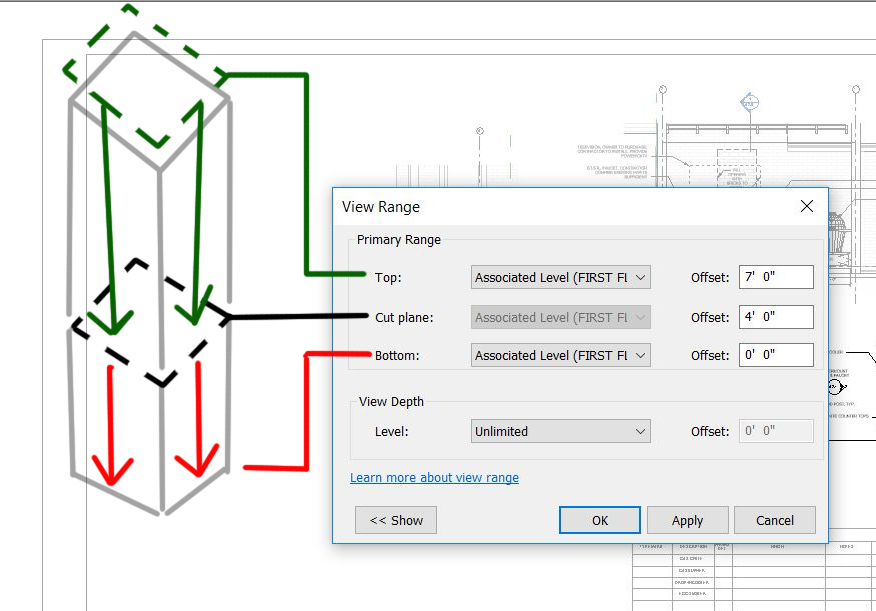
- the CUT PLANE box controls the elevation at which you want to cut your model. In this example, I am cutting my model 4'-0" from the associated level. My view will show everything from 4'-0" downward to the BOTTOM.
- ASSOCIATED LEVEL: what is that? The ASSOCIATED LEVEL is the level you choose to associate the views from. Here I am choosing the FIRST FLOOR. You may choose a datum level that best suites what you are trying to show.
- the BOTTOM is set to 0'-0" so my view stops there with exception of model elements within the VIEW DEPTH, see below for more information on VIEW DEPTH.
- the TOP is a tricky to visualize, because by principal if you are cutting through something, why would you need to see anything above the CUT PLANE? But this is architecture and we know that we need to see things above the CUT PLANE for the sake of showing locations. Setting the TOP at 7'-0" means elements with super powers will show up in the view. The elements I am referring to are programmed into the software to show up in the TOP portion of the view. These elements are WINDOWS, GENERIC MODELS and CASEWORK.
- the VIEW DEPTH is an adjusted range outside of the primary range where part of the model will be illustrated using a <BEYOND> line by default. There are exceptions. FLOORS, STRUCTURAL FLOORS, STAIRS and RAMPS within the VIEW DEPTH will appear as their designated PROJECTION LINE. I guess these elements have super powers too!

I hope I provided a little guidance when setting up your views. If you are still having difficulty understanding the VIEW RANGE, the software help center breaks it down more thoroughly. Don't be afraid of the little blue links!
