Here's a flythrough rendering of a project we're currently working on in Mid-City, coordinating with structural, MEP and food service equipment consultants to create an information model that coordinated equipment in tight spaces, produced construction drawings and provided the zoomy experience you see here!
BIM
Journal of a Revit Noob: 3 Reasons BIM Offers Architects an Opportunity for More Purposeful Design.
in BIM
In the early 1980's, AutoCAD was introduced to the market and began facilitating construction documents for architecture and engineering firms, promising quicker drafting times. The days of hand drawings were coming to an end. Younger architects managed the drafting process while the more experienced architects designed, managed day-to-day coordination, and produced hand-sketches or red-lines. This created a generation of young architects who considered projects first in plan, then elevation, then details - as they were handed down to them to draft - this was my generation. So much of our energy was spent perfecting the minutiae of the drawing set and less time was given to the initial design concepts. I felt as if my generation only spent about 10%-15% on design and 85%-90% on construction drawings. This was before BIM.
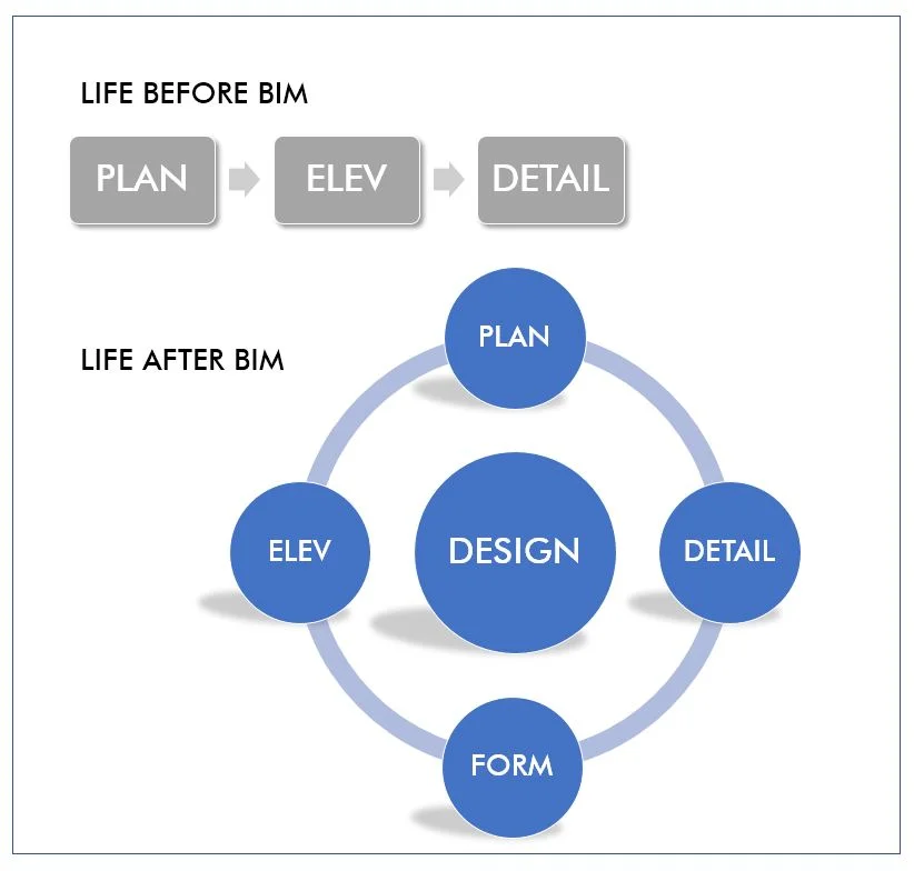
What I have realized in my first year of learning BIM in my practice is that we are spending about 50% of our time designing and only 50% of our time managing the construction set, which is yielding more thoughtful architecture. I can't believe I am saying this because one year ago, I told my best friend/architect buddy that there was no way I was learning the software. I am 14 years into my career. I'm almost to the point where I can hire interns. I really don't see the point.
What I have learned in the past 8 months has been that I can have more purposeful projects. Instead of having to develop ideas first in plan format, then elevation format, then in detail, we design holistically, shifting all our energy from rote production tasks to developing our design's expression, character and forms in 3d. My husband and business partner told me this would be the result of BIM, but I didn't really believe him at the time. Now, I am totally on board and excited about our future projects. As a small design firm in a competitive environment, we need to work fast, cheap and well – to hell with the old saying that we have to pick two. But we really all are capable of that in delivering a design product, by working smart!
The Bat Signal Construction Drawing
in BIM, Tips & Tricks, Workflow
One of the adjustments to make when using BIM for drawing production after years of AutoCAD is remembering that you have all of this information in three dimensions at your fingertips, if things are modeled correctly. Gone are the days of switching to ISO mode and redrawing a detail with 3 locked axes, which just describing is making me both sleepy and angry.
Little axos were used often to show corner conditions or transitions when 2D got too crowded or just didn't cut it. Though time consuming, they were often my favorite details, and contractors' as well, because of the instant communication of an idea that might have taken 3-4 convoluted 2D details to convey, or 15 minutes of a meeting.
Integrating these into your construction drawings in BIM is stupidly easy and affords all kinds of increased creativity in showing how things go together. One of my favorite methods is what I've taken to calling the "Bat Signal" method. You're familiar with the concept of the Bat Signal, unless your only experience with Batman is with the more recent, heavily emo iteration of the Dark Knight. If so, Google Adam West and lighten up; and also, see below:

Bat signal, circa 1970
One problem with the old CAD axo method, and with industry standard construction drawings, is - how do you callout a 3D detail on a 2D plan or section? Section markers don't cut it and callout bubbles can work but the connection can be lost between the larger and smaller scales, especially if the detail is on a separate page.
Enter the 3d callout, Bat Signal Method:

Holy Parameters, Batman!
Simply constructed with two frameless views and some detail lines directly on the sheet, this arrangement solves several visual communication problems at once. And once you use this a few times, you start realizing how many places you can use this to demonstrate complex intersections. And you start getting encouraged to model these correctly to create useful diagrams. It's a self-perpetuating cycle that encourages 3D thinking all around.
Journal of a Revit Noob: View Range Illustrated
in BIM, Revit, Tips & Tricks
I was having a little difficulty understanding the VIEW RANGE settings which is an important tool in setting up your views, so I thought a visual guide may do me (and you) some good! I'll jump right into it.

- Double click into your view and refer to your PROPERTIES tool bar. You will see an "Edit" box under EXTENTS. Click it.
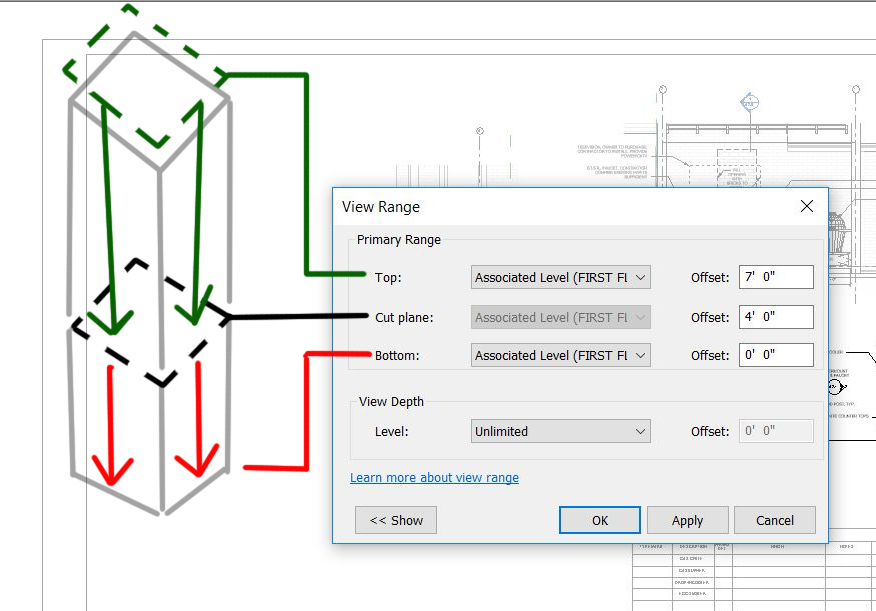
- the CUT PLANE box controls the elevation at which you want to cut your model. In this example, I am cutting my model 4'-0" from the associated level. My view will show everything from 4'-0" downward to the BOTTOM.
- ASSOCIATED LEVEL: what is that? The ASSOCIATED LEVEL is the level you choose to associate the views from. Here I am choosing the FIRST FLOOR. You may choose a datum level that best suites what you are trying to show.
- the BOTTOM is set to 0'-0" so my view stops there with exception of model elements within the VIEW DEPTH, see below for more information on VIEW DEPTH.
- the TOP is a tricky to visualize, because by principal if you are cutting through something, why would you need to see anything above the CUT PLANE? But this is architecture and we know that we need to see things above the CUT PLANE for the sake of showing locations. Setting the TOP at 7'-0" means elements with super powers will show up in the view. The elements I am referring to are programmed into the software to show up in the TOP portion of the view. These elements are WINDOWS, GENERIC MODELS and CASEWORK.

- the VIEW DEPTH is an adjusted range outside of the primary range where part of the model will be illustrated using a <BEYOND> line by default. There are exceptions. FLOORS, STRUCTURAL FLOORS, STAIRS and RAMPS within the VIEW DEPTH will appear as their designated PROJECTION LINE. I guess these elements have super powers too!

I hope I provided a little guidance when setting up your views. If you are still having difficulty understanding the VIEW RANGE, the software help center breaks it down more thoroughly. Don't be afraid of the little blue links!

Journal of a Revit Noob: Defining Views For Sheets!
in BIM
I am a few months into Revit Academy and my emotions towards my progress is like December weather in New Orleans, constantly changing and confusing! I still find myself learning new things. How can I still be learning new things, it's been five months, but then I remember Revit is a language. Practice, Practice, Practice!
Today, I am going to break down how to set up a production drawing sheet. I am assuming your BIM-Master-Husband has already created a model for you, as mine did.
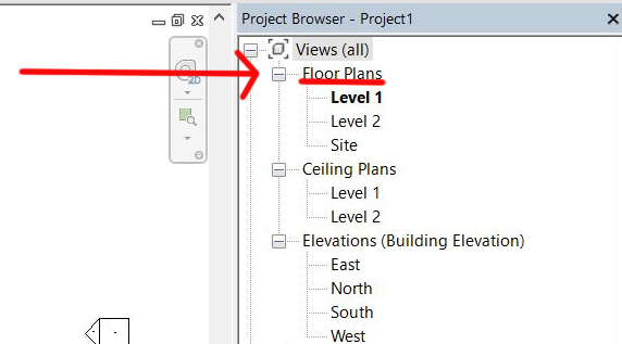
The PROJECT BROWSER is the index to the complex book you are writing, so let's start there. If you can't find it, and have no idea where it is hiding, go to your VIEW tab and to the far right of the ribbon, you will see User Interface - click it, and check off Project Browser. Voila!

All the views you've used to build that sweet model are listed there, and are categorized by type such as: FLOOR PLANS, SECTIONS, ELEVATIONS, 3D VIEWS, etc. Since you or someone have been working in these views, they may look sloppy and that's fine. These are, and will stay, your working VIEWS.
Working downward in your PROJECT BROWSER, you'll see SHEETS listed in the next section after the VIEWS. Setting up the sheets is pretty easy once you do a few. Right click on SHEETS and click new sheet. You'll be asked which TITLE BLOCK you want to use. Now, your file may or may not have a TITLE BLOCK family loaded; if not, you'll need to load one or make your own. Mine does, so I click on the one I want and there you have it - a new, clean, white, titled SHEET, ready for content!

Let's pretend you want to create a SHEET of floor plans, which will include a Floor Plan, Demo Plan, RCP and Roof Plan. Return to the top of your Project Browser, and look through all your working Views, expanding where the tiny plus signs indicate sub-views. Let's add a Floor Plan for Level 1. Right click the view and duplicate it. Select the copy you just made and drag that sucker onto the new Sheet and click to place it.

Modifying the FLOOR PLAN is easy once you familiarize yourself with the PROPERTIES window. The PROPERTIES window is like my Revit to English translation book. To navigate through it, make sure you are actually inside the VIEW by double-clicking into it. The PROPERTIES window should indicate the name of the VIEW at the top. Let's work downward from there.
- GRAPHICS will help set the SCALE of the view, DETAIL LEVEL, and remember VISIBILITY/GRAPHICS from my last Noob post. This is where you can modify what model elements, annotations, imports, and filters will be seen in the VIEW. Having fun yet?
- Next is UNDERLAY and being a noob, I haven't used this much yet!
- Working downward, EXTENTS helps crop your view.
- IDENTITY DATA is where you can set your VIEW TEMPLATE which is great when you are working in Construction Documents where you will have many views of the same nature, i.e. more than one ELEVATION, more than one SECTION, etc.
- PHASING is the last category in the PROPERTIES window. Here you'll set what phasing information you want the view to show, such as how to show NEW, EXISTING, or DEMOLISHED elements.
Some of the most frustrating parts about setting up views seem like they should be the easiest things, things like "where is the DRAWING LABEL?" Sometimes mine are floating out in space and I have to play around with grabbing it and pulling it into a reasonable area. I have to get aggressive with that DRAWING LABEL.
You will repeat this for each DRAWING you want to place on the sheet. Are you thinking, "Where are the demo view and roof plan you talked about?" Sometimes you need to make those DRAWINGS with just a standard Floor Plan VIEW, just with different settings. Copy and paste the FLOOR PLAN VIEW in the PROJECT BROWSER, rename it and adjust what you see in the PROPERTIES window - it's that easy! Yeah Right! Five Freakin' Months!!
Here's a quick tip about line weights and viewing your DRAWINGS while setting up SHEETS. Sometimes it's tough to see what's going on when you zoom way in. If your drawing is looking like one big ink-blob, use THIN LINES. Clicking on this will make you see all lines at same thickness; it may be easier for you to work with. Click it again to turn it off and see the actual line weight properties of the elements.
